Preface/Disclaimer
This is a fairly difficult repair. Like, you will need a multimeter, a temperature controlled soldering iron/station and possibly hot air, you have to be confident soldering and de-soldering through-hole and potentially SMD components, and you may need to be proficient at PCB repair, depending on the extent of the damage.
If this isn’t you, I’d suggest finding a local electronics repairer that can do board level repairs. I’m sure a lot would be willing to take the job on if you can either explain what needs to be done, and/or show them either this or one of the resources linked at the end. It may cost you a pretty penny, hell there’s every chance it costs as much as or more than another used cluster, but you avoid the risk of making things worse by diving straight into the deep end, and you can be confident it’ll be a long term fix, as opposed to buying a used cluster that’ll likely succumb to the same fate.
If you have a spare cluster or something so there’s no risk, or are willing to jump in the deep end and run the risk of making things worse then feel free, but I just want to make it clear that this can grow into a fairly advanced board repair if you do need to repair the traces. This also isn’t guaranteed to fix your cluster! It fixed mine, and will likely work on quite a lot of dead clusters, however there’s other potential points of failure, and theoretically severe enough corrosion could also damage other components even if this was the initial issue. Keep this in mind before diving in.
Intro
For a bit of context, I come from a BMW family. My dad drives one, mum drives one as a result, and therefore I’ve ended up with one too. The issue with this is I don’t really come from money so they were all bought secondhand, and most people are aware of how, uh, how do I put this? Problematic older used European cars can be, and among the numerous issues that have come up over the years, gauge clusters randomly dying in the E46s has interested me the most.
They just die sometimes without a whole lot of rhyme or reason, and it’s surprisingly difficult to find info given these are very popular cars — the generally accepted repair is just to replace the whole cluster, which comes with its own set of issues; mostly that most if not all used clusters will eventually suffer the same fate, but also that not all clusters work on all cars. You will need to code the replacement cluster to your ECU if you want the correct mileage and no tamper dot, and Motometer units also won’t work/work properly on some late models due to a change in signaling. This means you may have to do a little minefield navigation to find a Bosch cluster if you have a late build; I don’t remember the exact cutoff but I believe it’s sometime in the first half of 2003.
Why, and why now?
Predictably, a cluster died. Two, actually, this is the second one to break in Dad’s car — it’s been on the way out for ages, hell, the speedometer broke months ago. This doesn’t really faze him since he has a quite frankly impressive ability to ascertain his speed just based off of RPM & gear within like 5km/h, but then this cluster died really hard. I believe it died so hard, in fact, that it’s the reason the car intermittently won’t start, but I’ll also get back to that later. For now, in the spirit of troubleshooting, I dug up the first cluster that died in this car, and proceeded to give it an autopsy.
Hypothesis and diagnosis
Before I even dug up the original cluster, I was fairly sure I knew what the issue was. For the uninitiated, there was a whole debacle in the mid 2000s surrounding capacitors, and the fact a significant amount of capacitors made between about 1999 and 2007 had a tendency to explode and spit acid everywhere. This led to not just the capacitors themselves failing, but the acid that leaks out then damages the board underneath.
With this in mind, I started to disassemble the cluster. It’s mostly fairly simple – You take out a few T10 screws on the back (though some clusters differ – I’ve heard some use a T15, both my Bosch and Motometer units used T10s, but have a variety of bits/screwdrivers on hand just in case.) Carefully work around the edges with your preferred pry tool – I just use a small flathead screwdriver, and you should be able to separate the back from the front housing, and then remove the PCB and gauges as a single assembly.
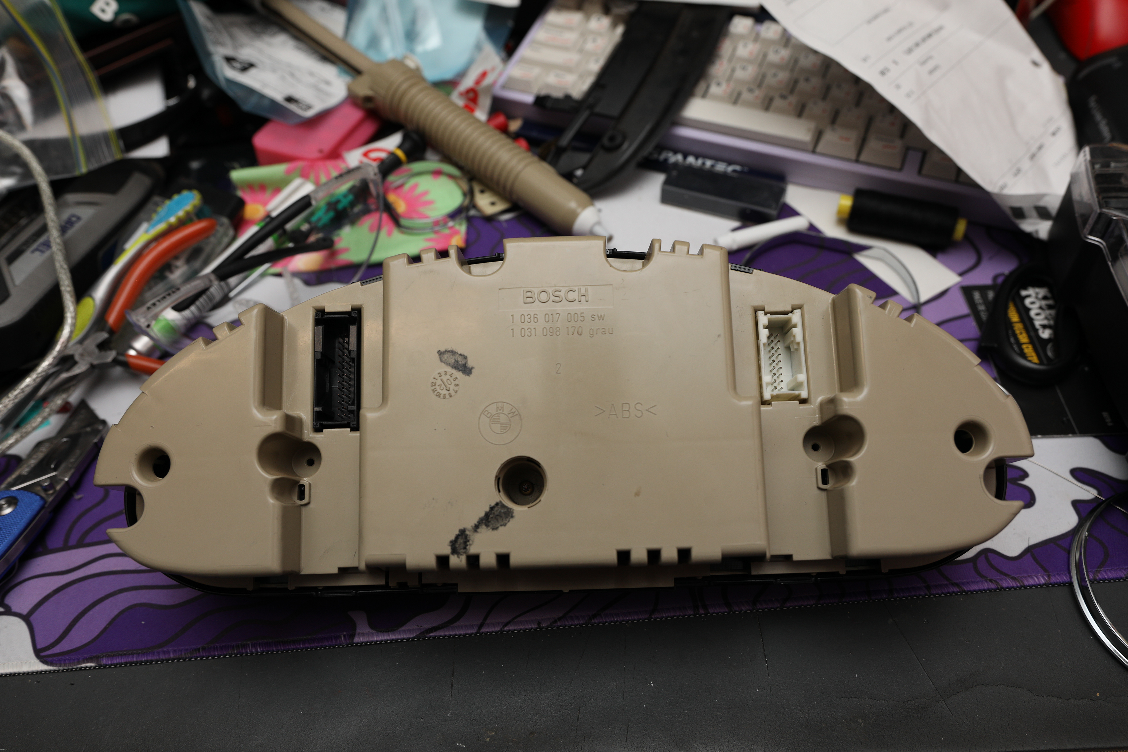
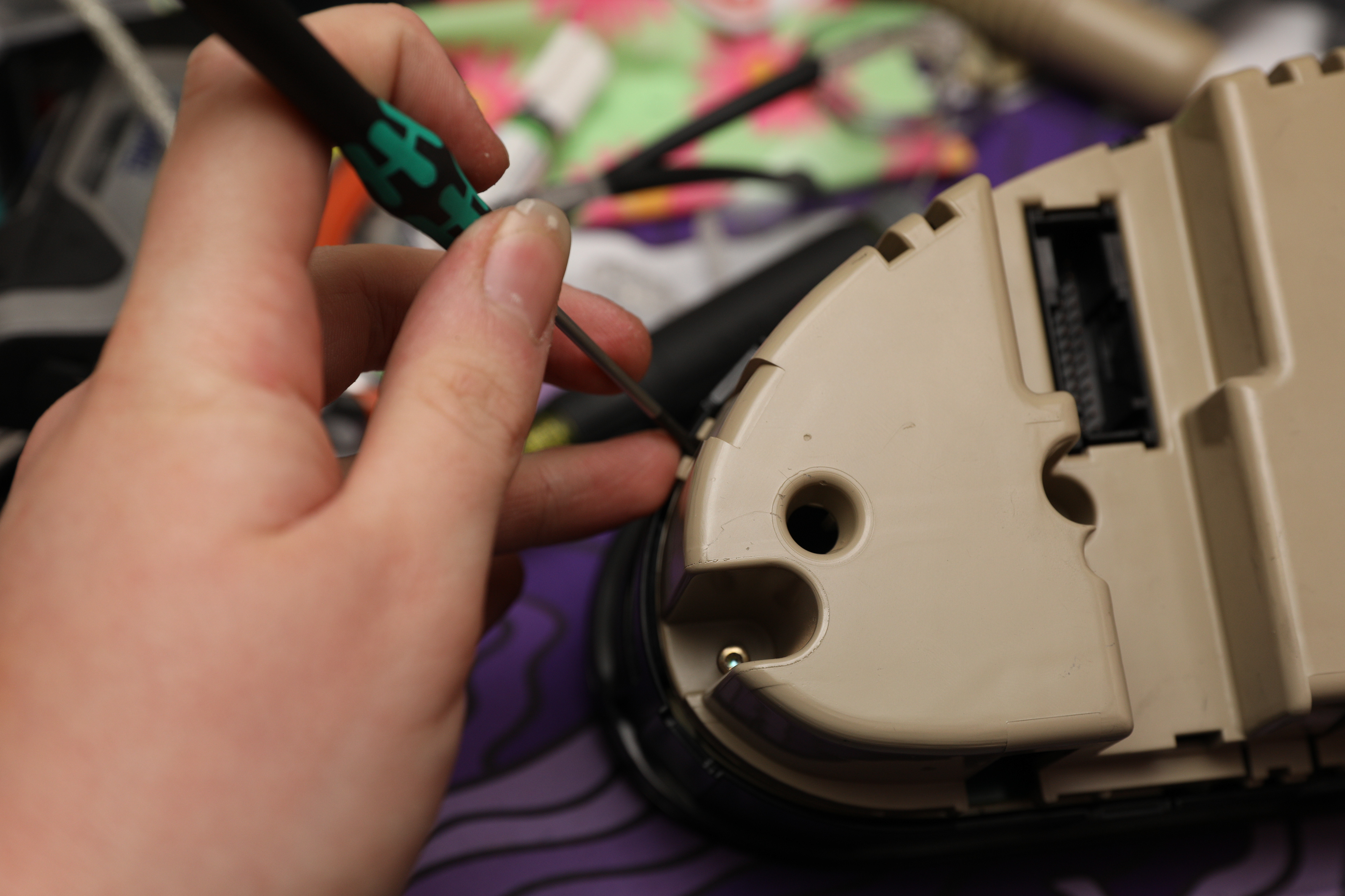
This is a different cluster, but the process is the same. Use a pry tool to release the clips, then the back pops off.
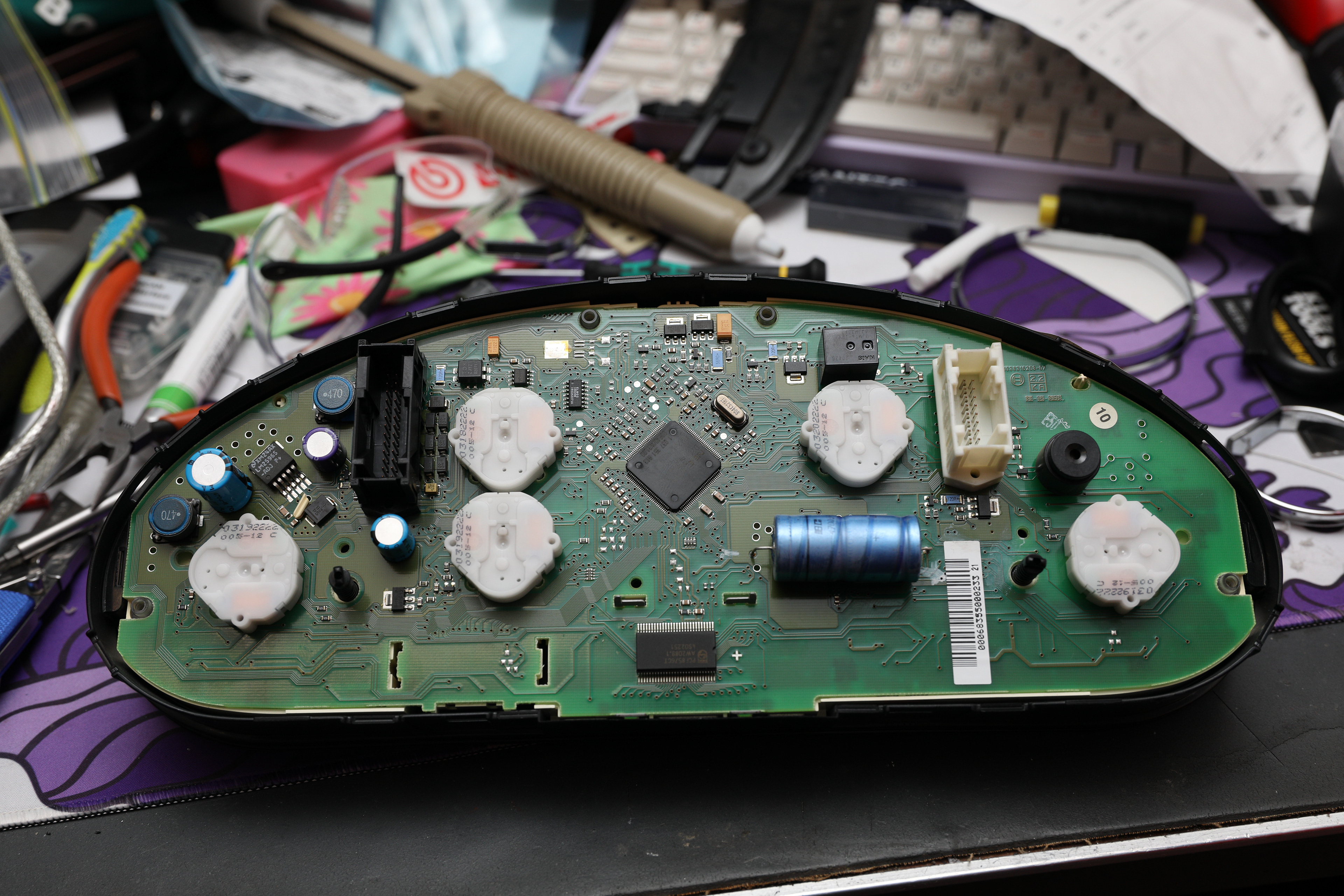
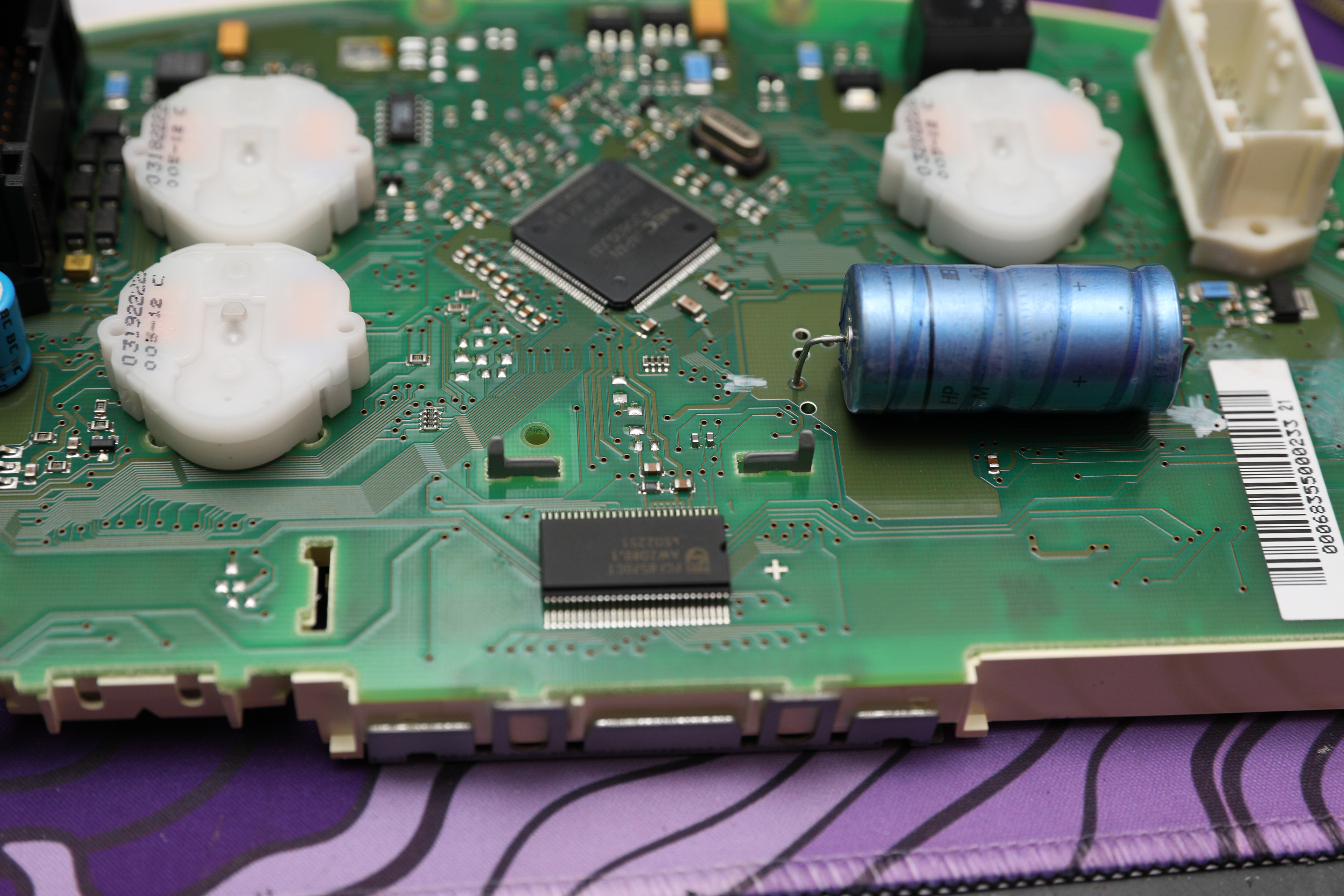
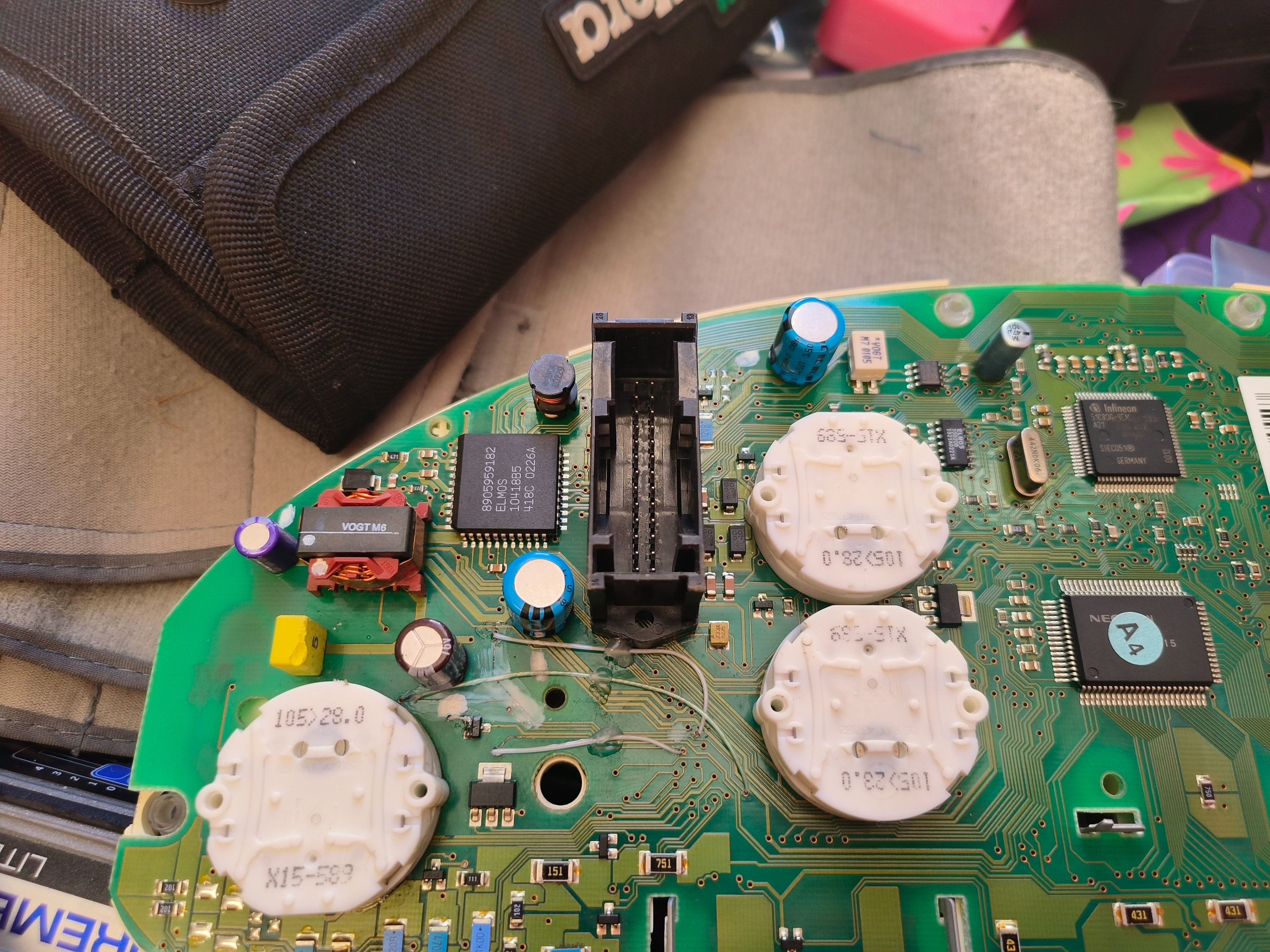
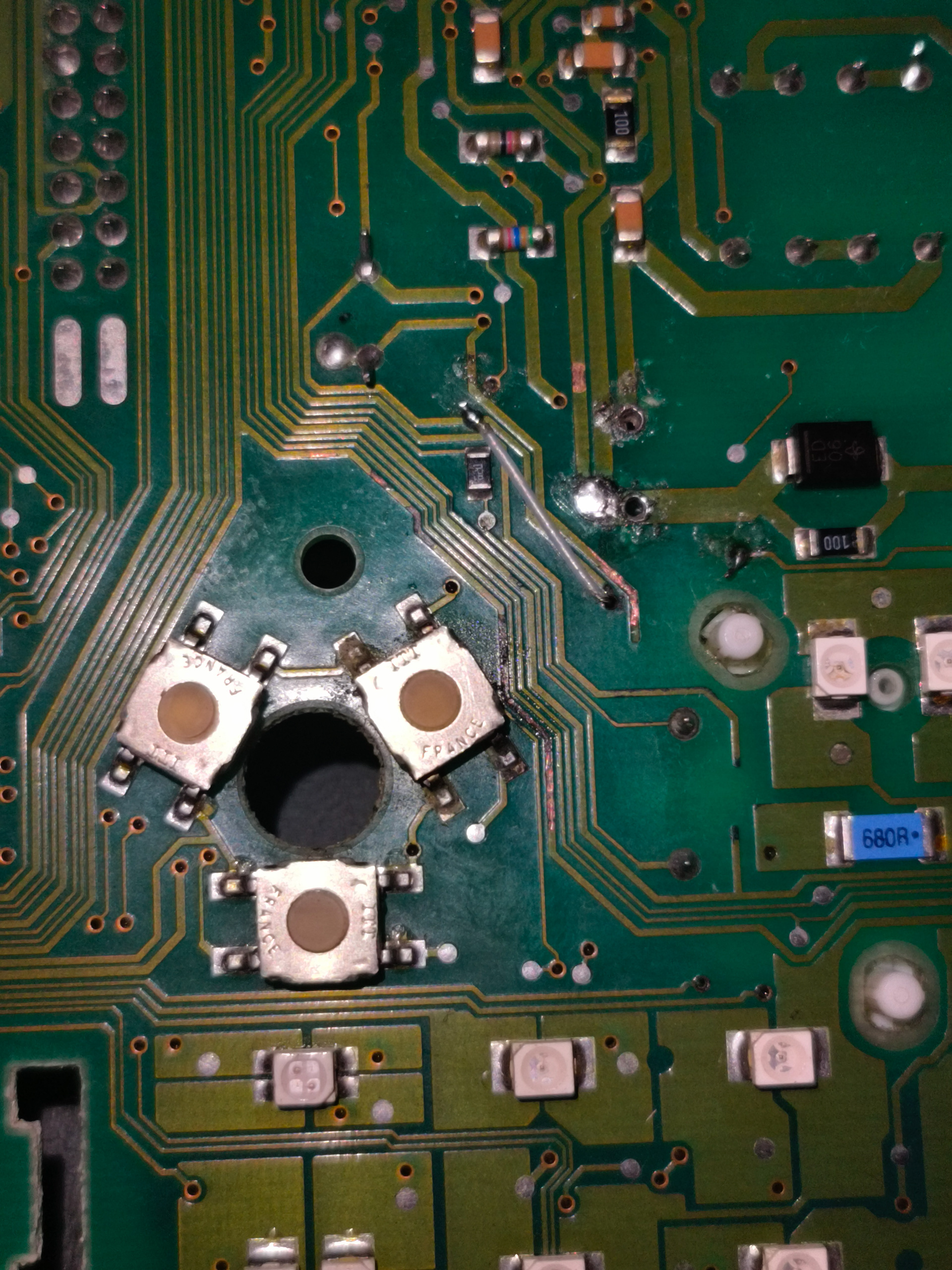
After separating the cluster itself from the housing, I can flip it over and inspect the circuit board itself, which revealed exactly what I suspected. The main capacitor had spilled its guts all over the board, taking out traces underneath it and causing chaos.
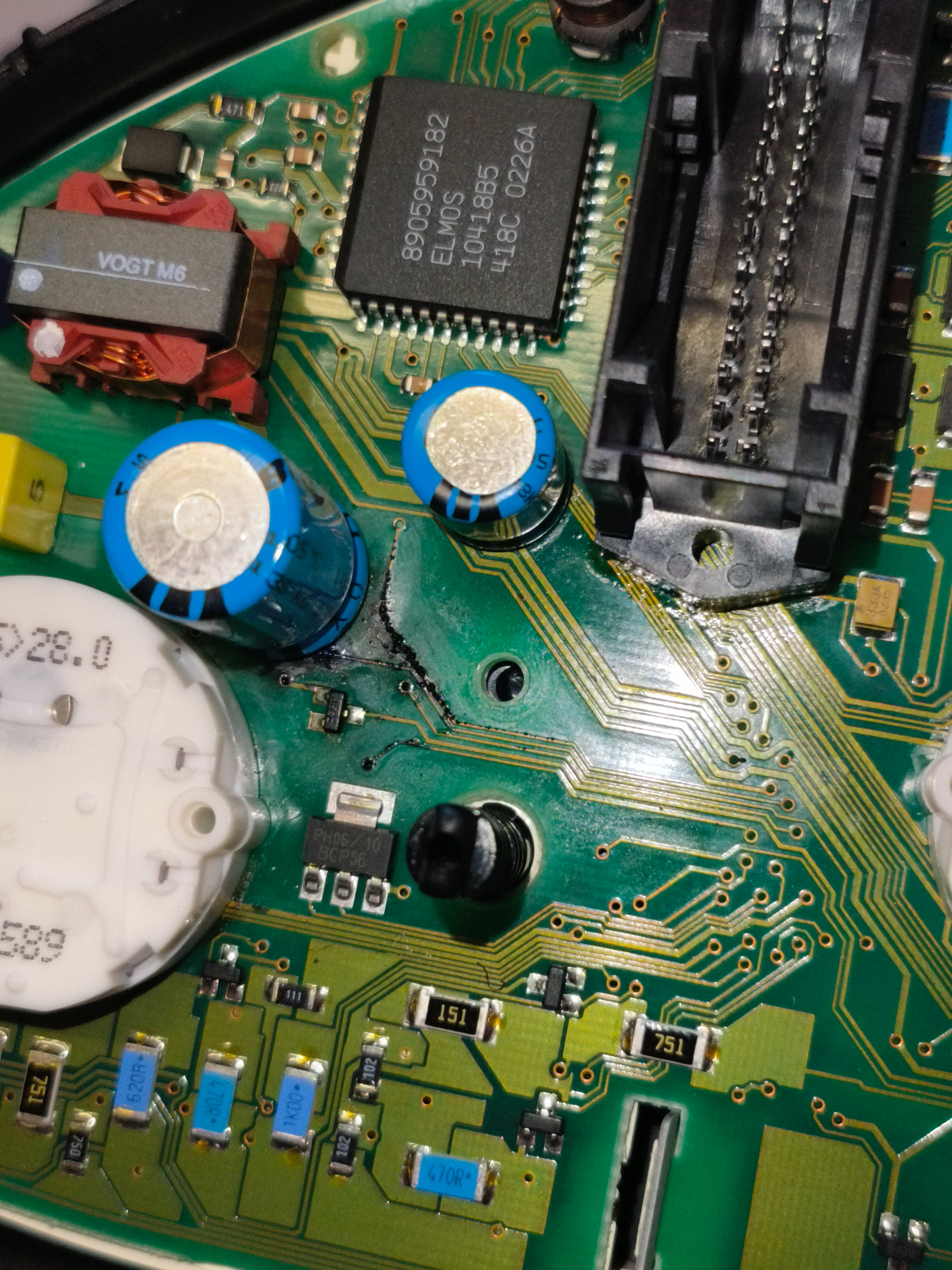
Note the black corrosion on the board. This is caused by the capacitor leaking.
Fortunately, this is an example where the damage is really easy to locate – there’s a bunch of corrosion around the capacitor, and the PCB is fairly simple, with lots of contrast between the fibreglass itself and the traces routed on top of it. This makes my job much easier.
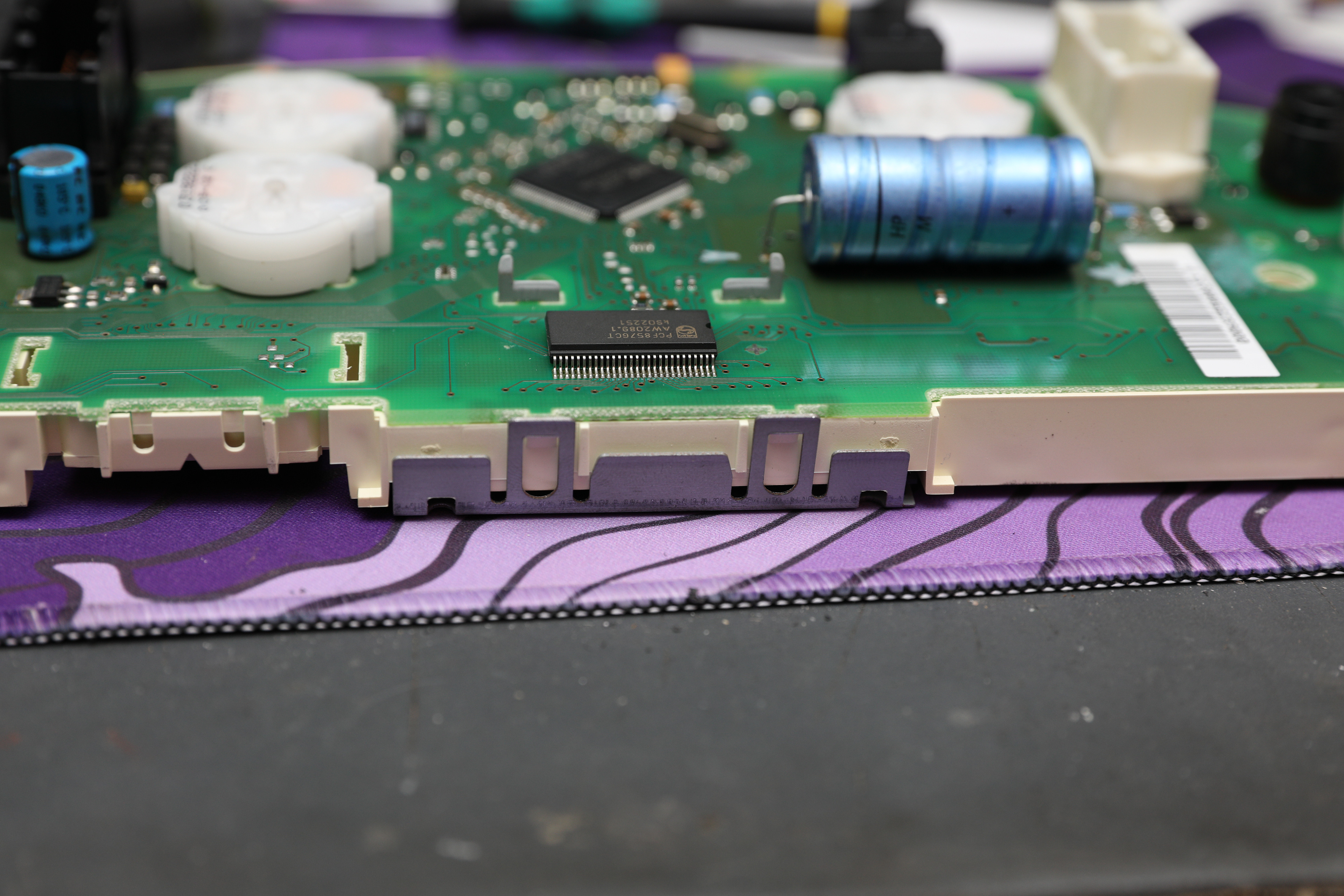
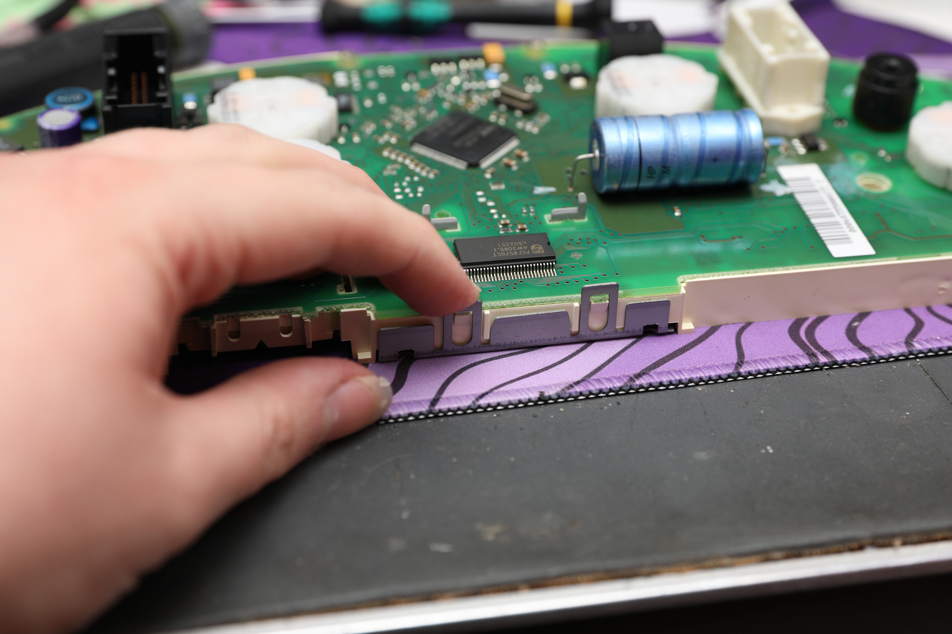
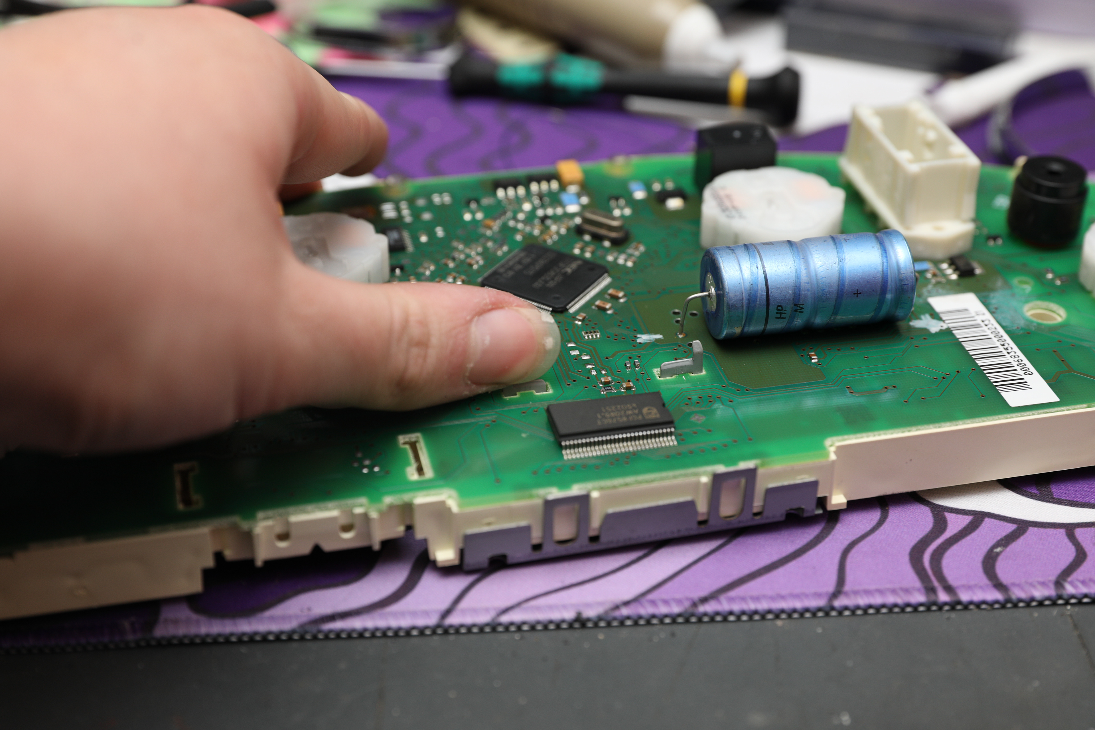
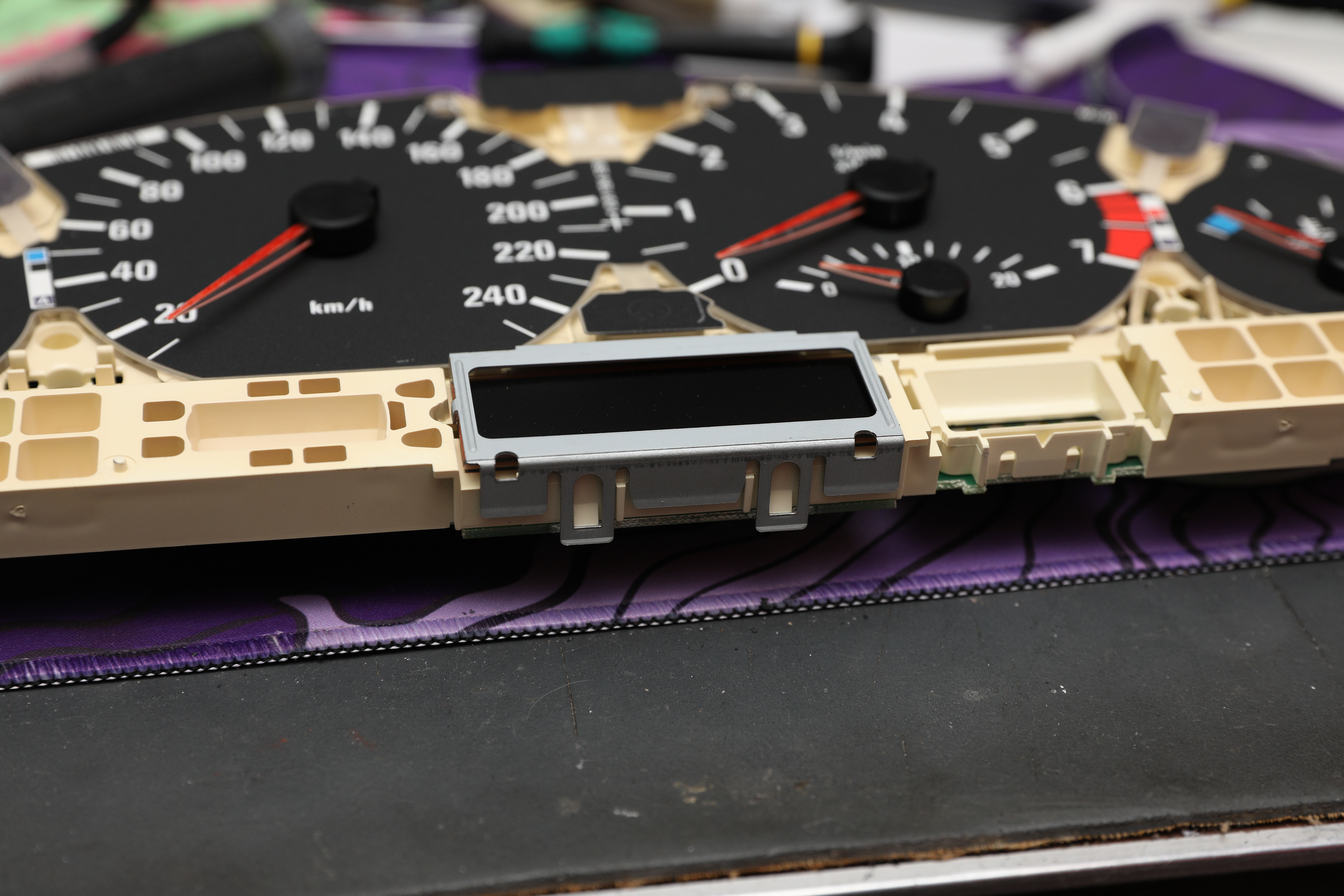
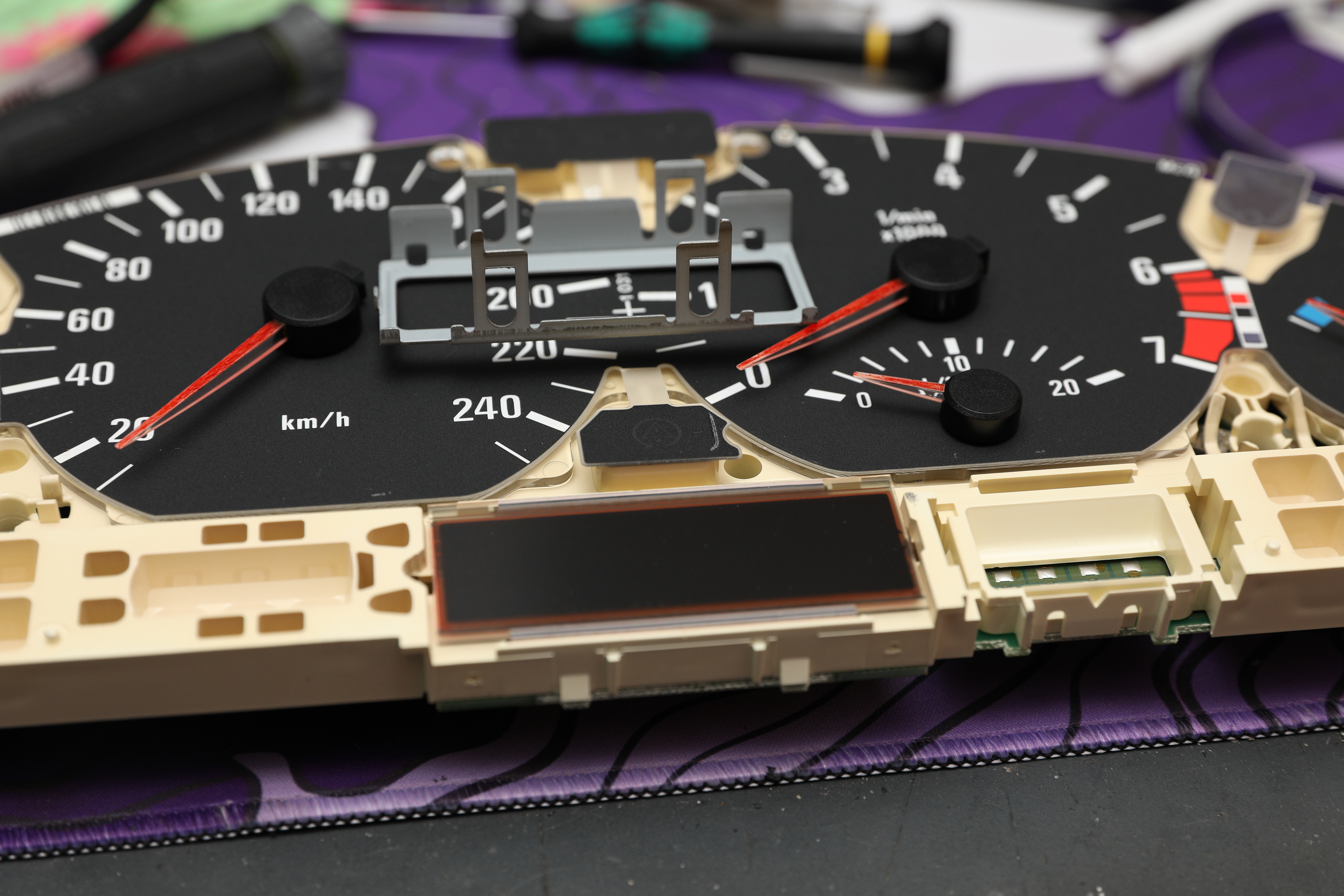
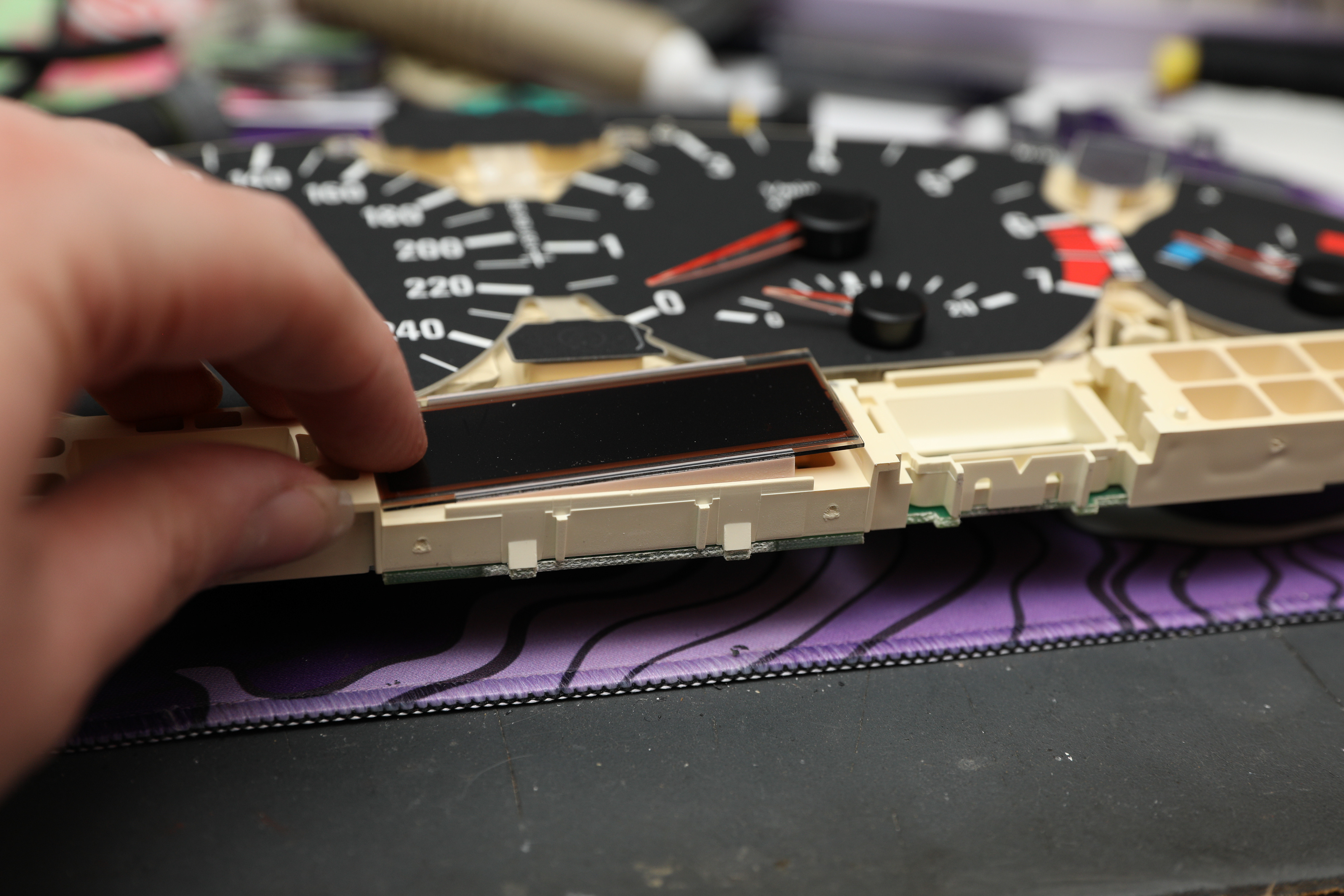
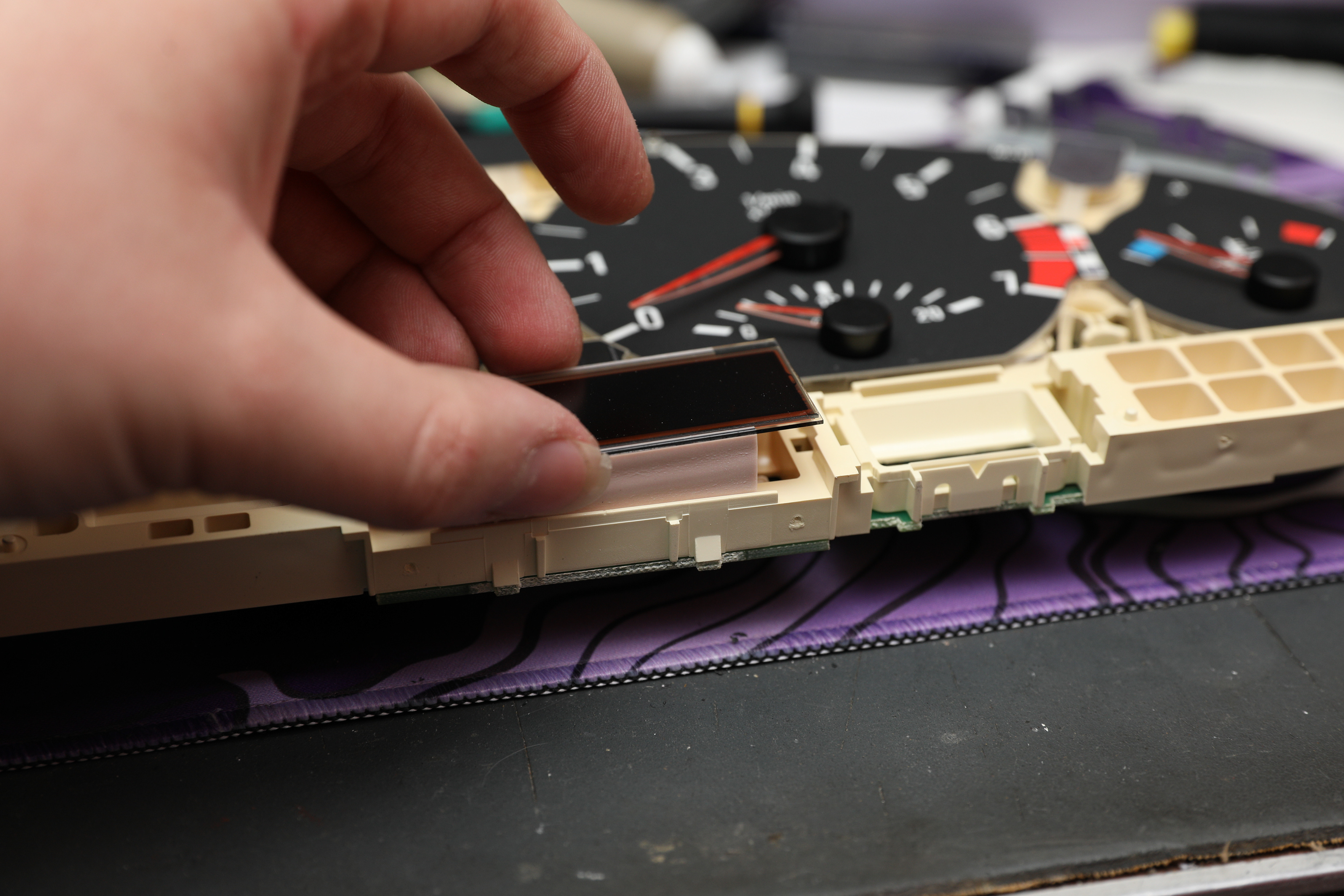
I now have to separate this PCB from the plastic section, which I start by removing the LCDs. These have small metal frames holding them to the board, which are VERY important because they rely on this mounting pressure to connect, and won’t function without them. You just have to pry the clips on each bracket outward so that they slip off the edge of the board, then you can remove the brackets, and you should be able to pull the LCDs upwards after – try to keep these in the same orientation you took them out in, since there’s not really any clues as to which way they go in. If you get it wrong, you don’t find out until you plug the cluster back in and the display is garbled and weird.
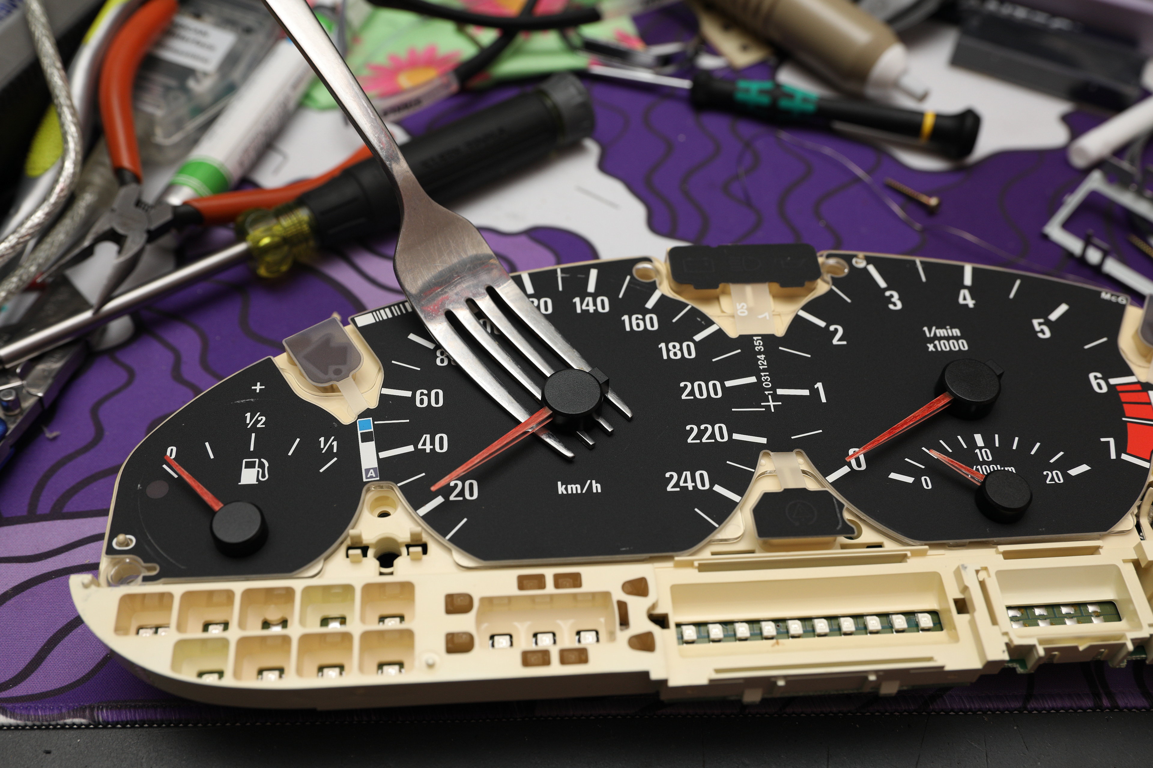
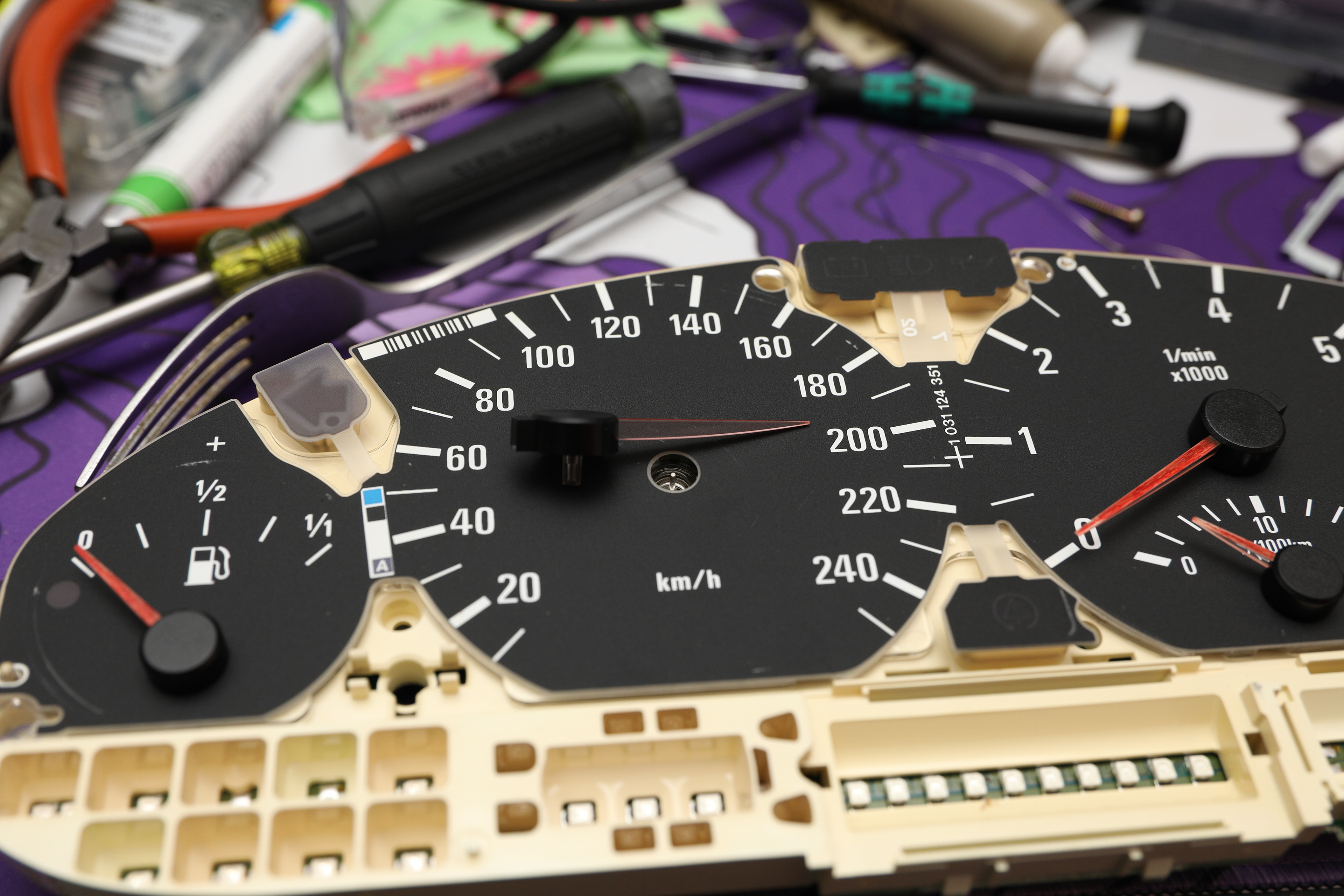
Once this is dealt with, remove the needles for the gauges. These are spiteful things, I broke the little centre cap on every single one of them on my first cluster, though had no issues on the second. Once those were gone I could lift the needles off with the end of a fork, getting one prong on either side and prying up to pull the needle up. (Using a fork is VERY likely to scratch the face of your gauges – I don’t care that much personally, I just wanted to get it working, but if this bothers you use a plastic pry tool, preferably one you can get all the way under and pry evenly with.) These can be annoying, and can be even worse to get back on.
Repairs
The first port of call is to properly inspect the damage. Clean the area, remove the offending component, and see what needs to be repaired. I only removed the main 470µF capacitor for the time being, since none of the other capacitors had visibly leaked, and upon testing them with a multimeter they all tested roughly within spec. For the time being, I left them in place temporarily for testing purposes. (I could also have left them in permanently if I was really lazy, but there’s no point – capacitors are cheap, and when one has leaked already I’d rather just not run the risk.)
The damage actually isn’t too major here (I meant to take a picture when I desoldered the capacitor but forgot, the earlier one shows it well enough anyway) – there’s a few severed traces and a couple of blocked vias (which are like a little copper tube, they just carry electricity so you can connect traces on opposite sides of the board). Fortunately since both cluster OEMs used green solder mask, it’s fairly easy to just follow the traces from point to point and test them by using a multimeter in continuity mode.
I could mostly just test from via to via on my board due to the specific traces that were damaged, but otherwise you can just scrape the green solder mask on either side of the damage until you have two copper points to test. You’ll likely find that some of them are severely corroded enough that after cleaning, you scrape off some corrosion and there’s no copper left under it. This can seem intimidating, but just follow the trace, and solder a wire in place to bypass the damaged section. How you choose to approach this doesn’t really matter, I prefer to go from via to via where possible to take as much of the already compromised trace out of the equation as I can, but realistically as long as you have two solid solder points it really doesn’t matter. Just scrape off some solder mask, get enough heat into the board, and make sure you have solid connections on either end.
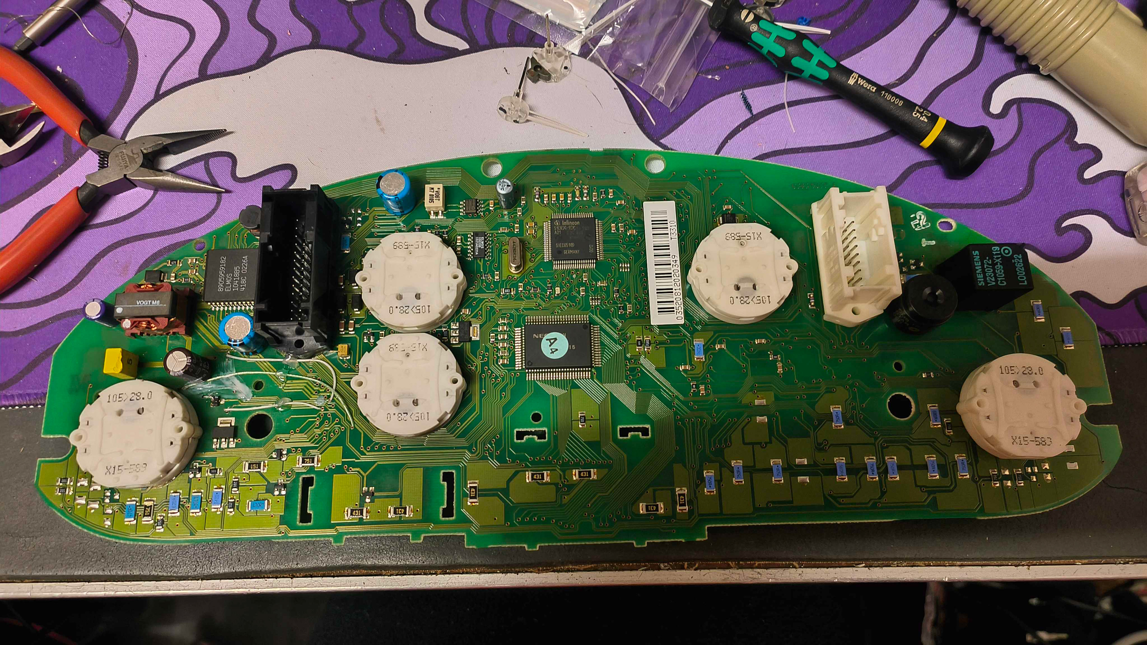
I'll be the first to admit - this is far from the cleanest repair ever. However, it works so I don't really care.
Once I’ve touched up the traces, the next step is replacing the capacitors. My Motometer unit had four – a 10V 68µF, a 35V 470µF, and two 35V 220µFs – all radial electrolytic capacitors. Bosch units differ, and need one 35V 470 µF, one 10V 220 µF, one 35V 220µF (all radial electrolytic also), as well as an axial 25V 4700µF. I will, however, note they’re also not that picky – I stupidly ordered 330µF capacitors instead of 220s, and it still works perfectly, I just had to cut up the back for it to close with them. Don’t do that though; be smarter than me and actually double check before you buy.
Anyway, this is the easiest part of the whole process. De-solder the old capacitors, and solder the new ones in their place. I’d also suggest marking the ground leg on the PCB (this is the side of the capacitor with the stripe down it) using a drawing implement of your choice, just to avoid forgetting which way the capacitors face. If you forget anyway, it’s fairly easy to find the ground pin with a multimeter – find any other ground point, whether you use one of the planes or if you literally just probe different solder points for the capacitors until you find two with continuity doesn’t matter.
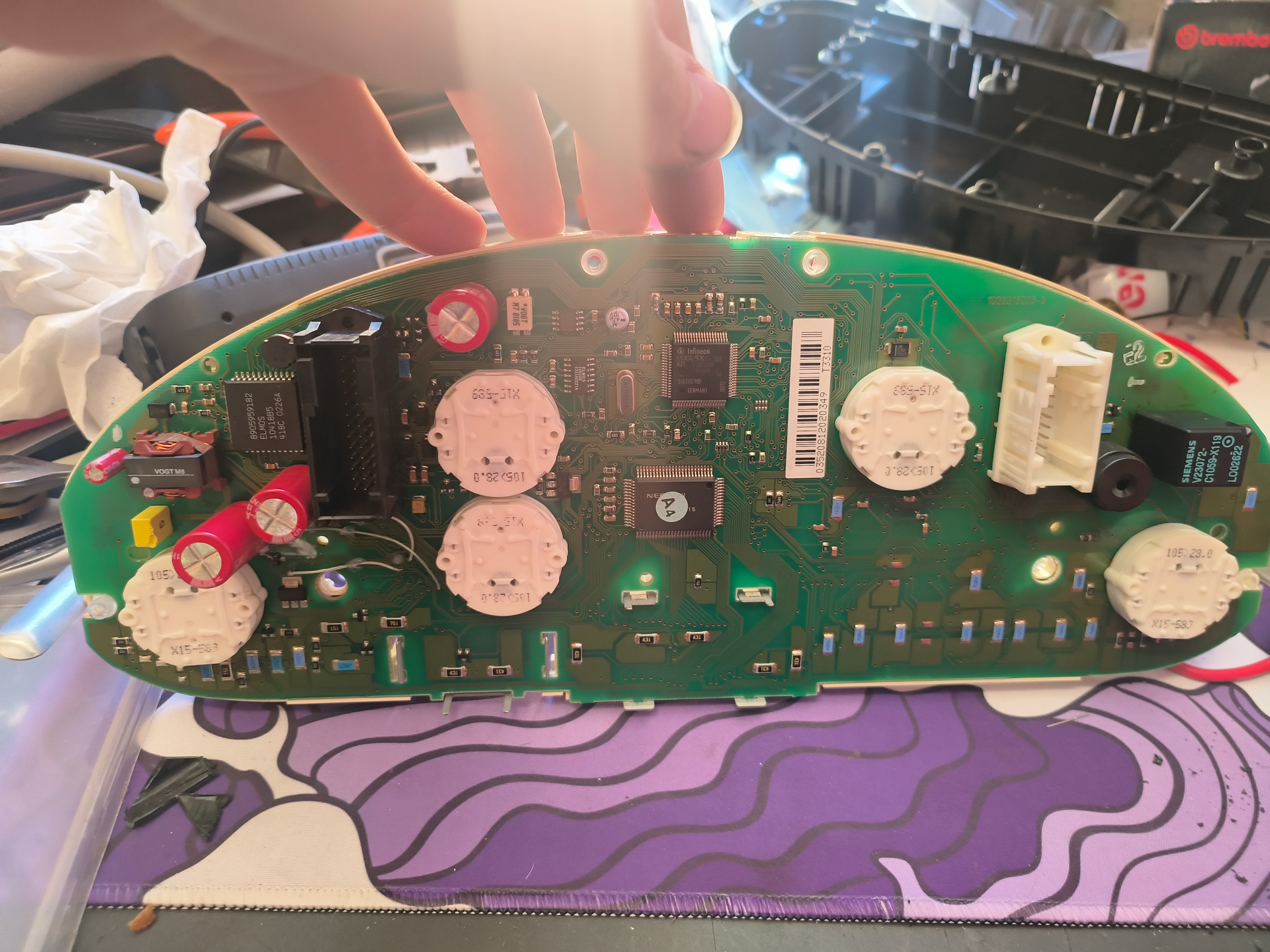
New capacitors! Notice the oversized one just to the left of the black connector. Oops.
Once the capacitors have been soldered in, it’s test time! Clip the PCB back into the plastic centre section, line up the LCDs, and clip their brackets back on. I’d also suggest you stick the needles back in now, just to make sure they still sweep. The easiest way I’ve found to do this and line them up is to put the little metal pin into the needle, with the little bit that sticks out facing towards the needle, so you don’t insert it too far (I actually think this is technically the wrong way, but it worked more easily for me). Then very gently line up the pin with the hole in its appropriate motor, and carefully press it in.
Don’t go too far, you’ll know they’re properly engaged when you can gently turn the needle, turning it counter-clockwise you’ll feel the motor hit its stop. You can also put the plastic cap back on. This is also the best time to line up the needle, - make sure the motor is at its leftmost stop, then gently rotate it further, allowing it to slip on the pin until it’s lined up with the correct marker. Don’t bother putting it back in the housing for now, since this is a good time to plug just this middle assembly into the car to make sure the board repairs have worked – no point fully reassembling the cluster if you’ll need to take it apart again anyway.
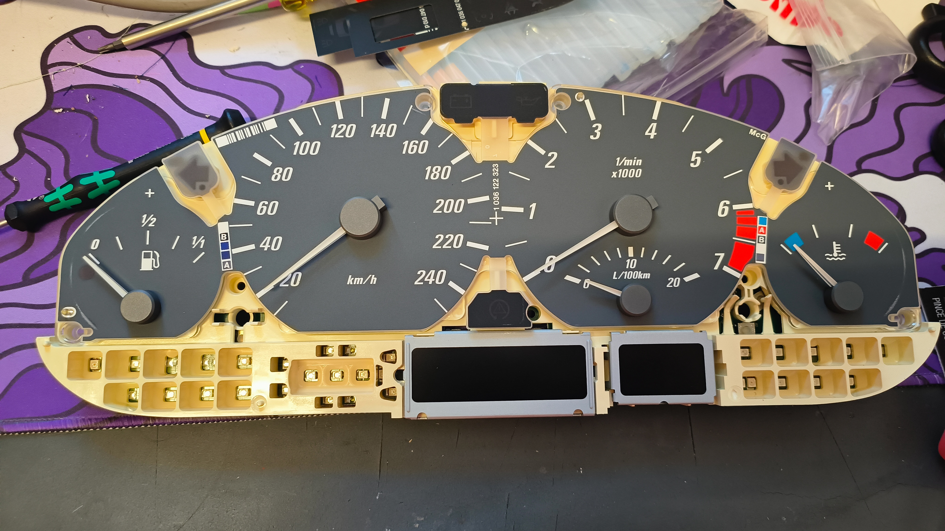
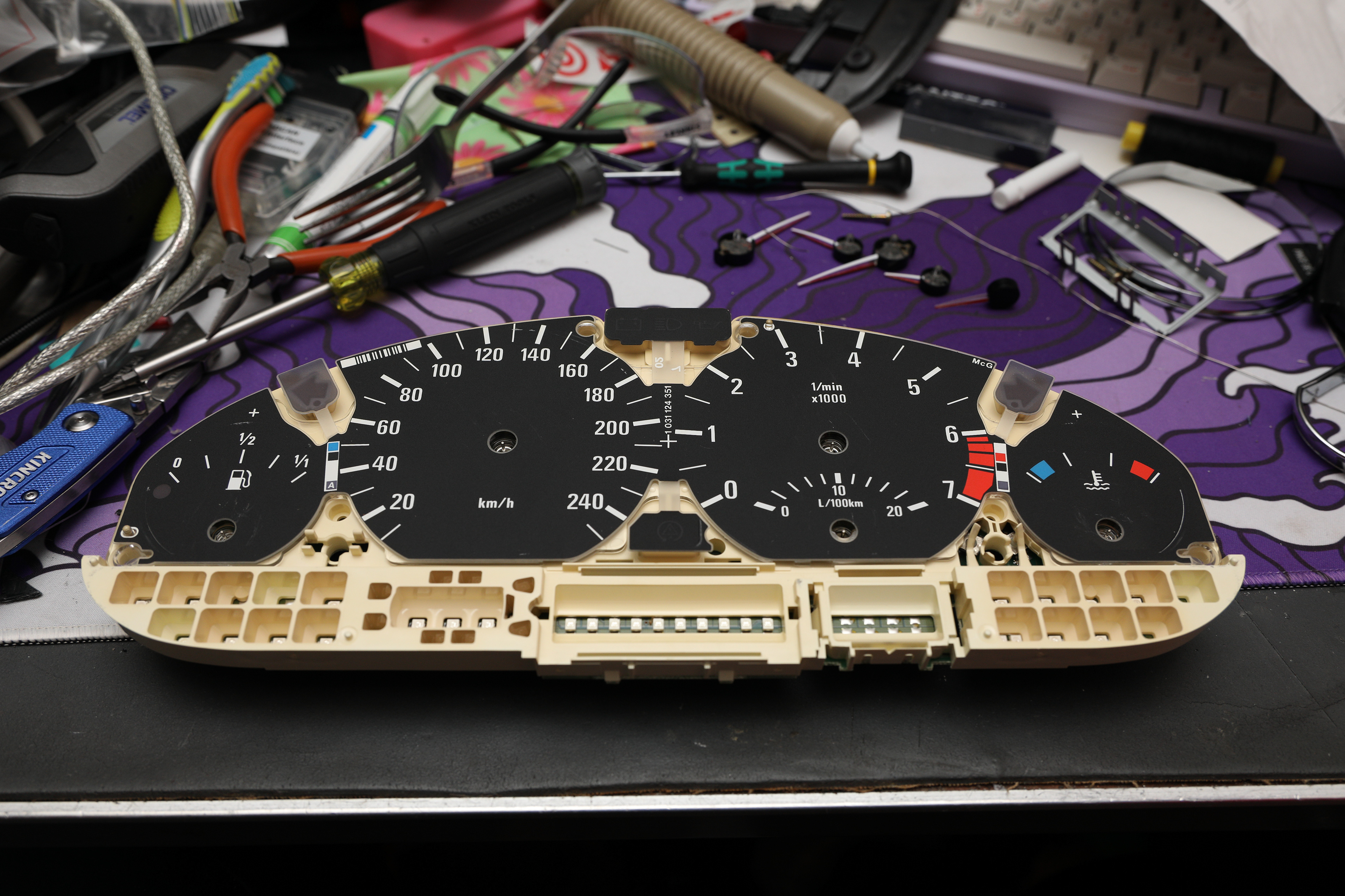
Partially reassembled and ready for testing
Testing
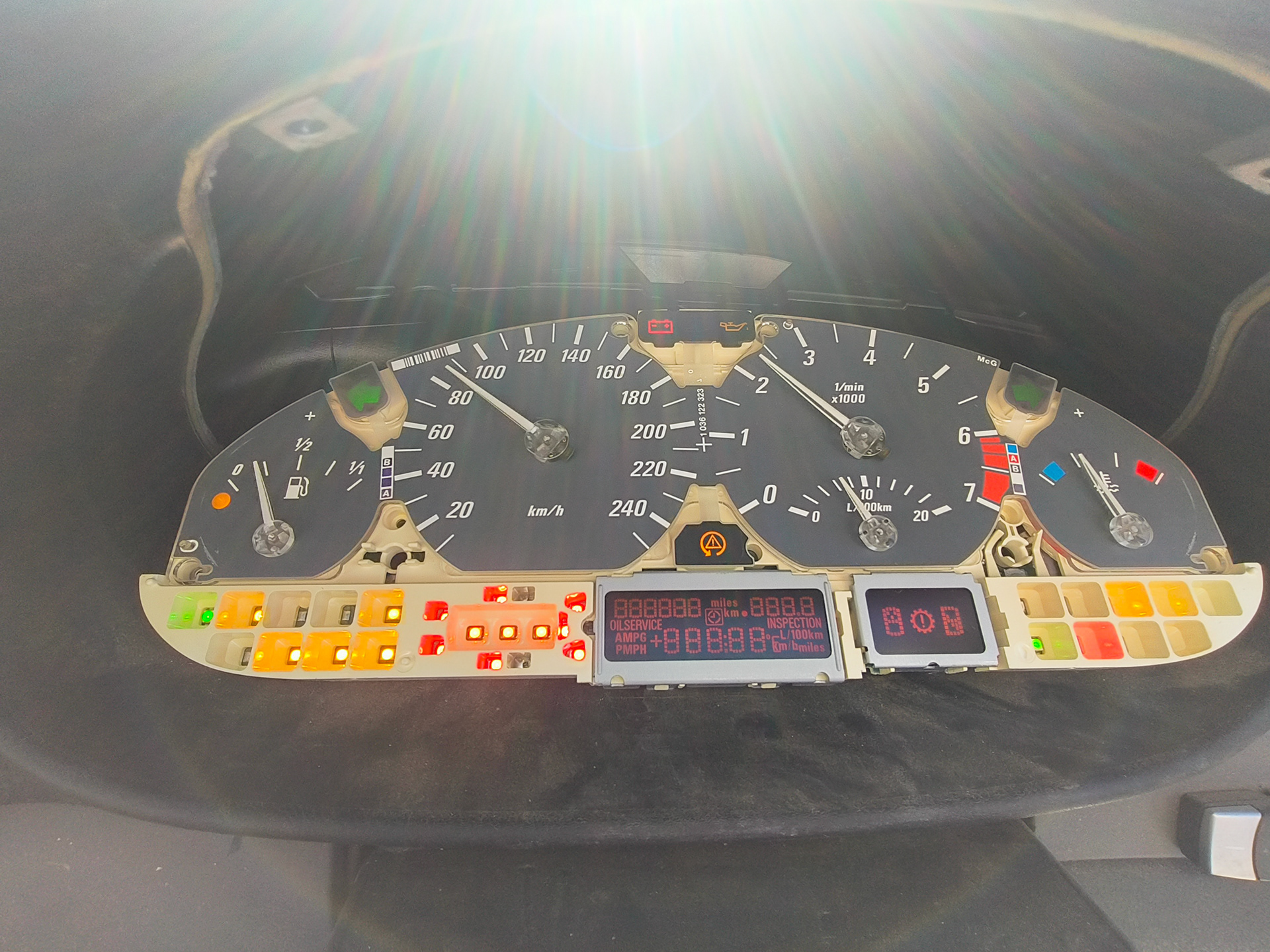
This is the home stretch! Take what you have out to your car, and plug it in, just as you removed it. Once it’s in, hold down the button for the tripometer reset using a screwdriver, and turn the ignition to the accessory position, keeping that button held down. If all has worked as intended thus far, it should say “Test” on the screen, with some numbers off to the right. Release the button when that comes up, then press it once so the 1 on the right hand side of the LCD counts up to 2, wait for a few seconds until it says 2.0 or 2.1, then press the button again.
All the gauges should sweep through their full range, and return to their original position. If all is good, start the car.
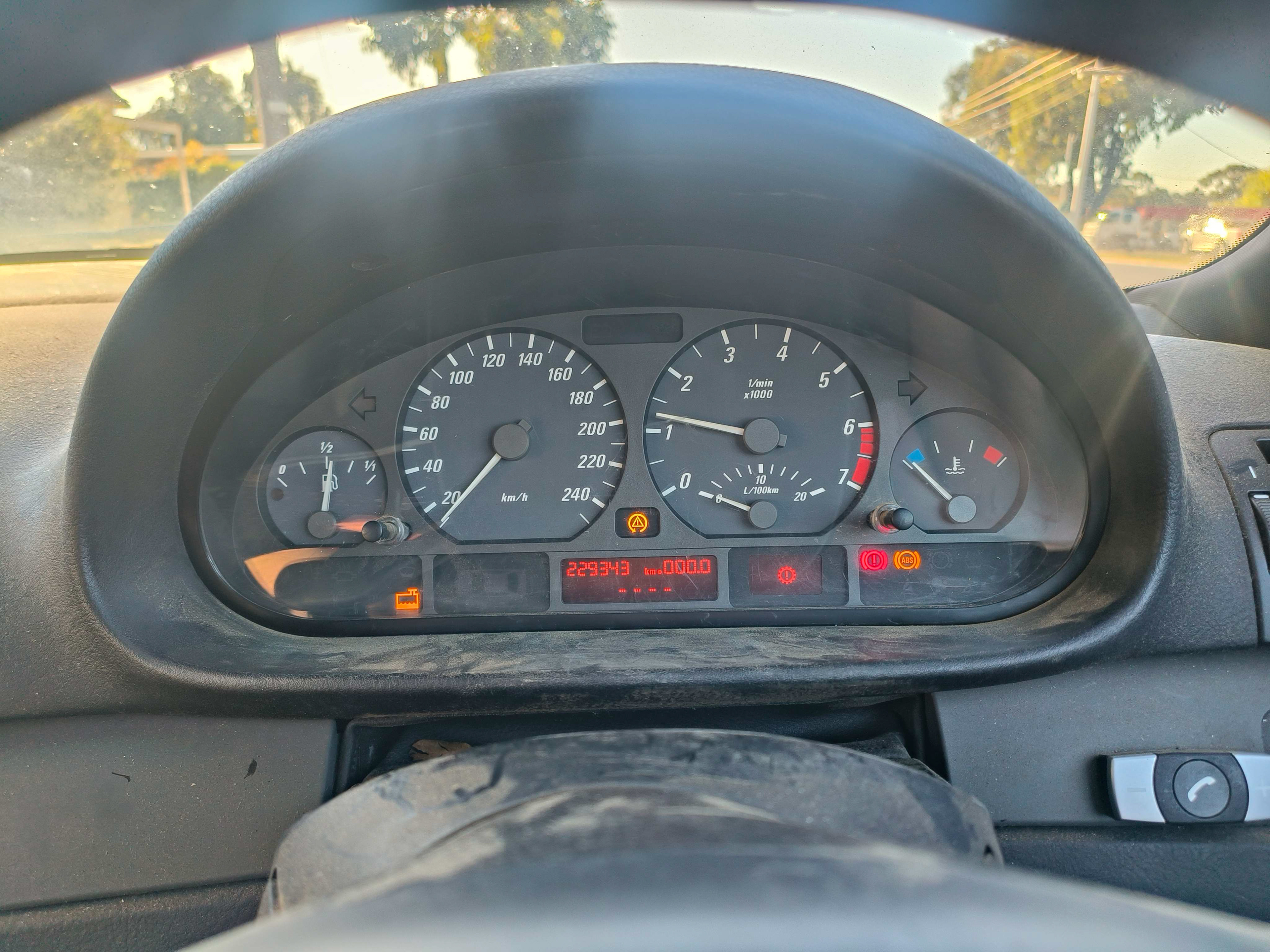
Excuse the glare, it was bright out and my phone camera kind of sucks
If all is not good, you can try a few things – if your LCD is garbled, try pulling it out and rotating it 180 degrees, when you put them in upside down they still light up, just they can’t display the signal properly. If some of the gauges don’t sweep, try pressing them in slightly further, just be careful since you can overshoot. If it doesn’t light up at all, go over all your repairs again with a multimeter and make sure you haven’t missed anything.
Once the car is running, make sure it responds to all inputs (scrolling through the OBC if applicable, also make sure your accelerator works fine.) Assuming that’s all good, and your speedometer, tacho, etc all work, you’re pretty much done!
Take this mid section back inside, put it all back together the same way it came apart (you also will probably have to glue those stupid caps back on if you care – I hot glued them, double sided tape or whatever will probably work fine too – this isn’t really a part that’s under significant load, just as long as they’re attached.)
Be very careful with the stems for the tripometer reset button & the twisty one on the right I forget it’s actual name, as they’re very fragile and the stupid barcode on the black plastic for your warning lights is in the way – I just cut it off with flush cutters since as far as I can tell it serves no purpose, but there’s probably a better way. Once it’s back together, reinstall and enjoy having gauges that work again.
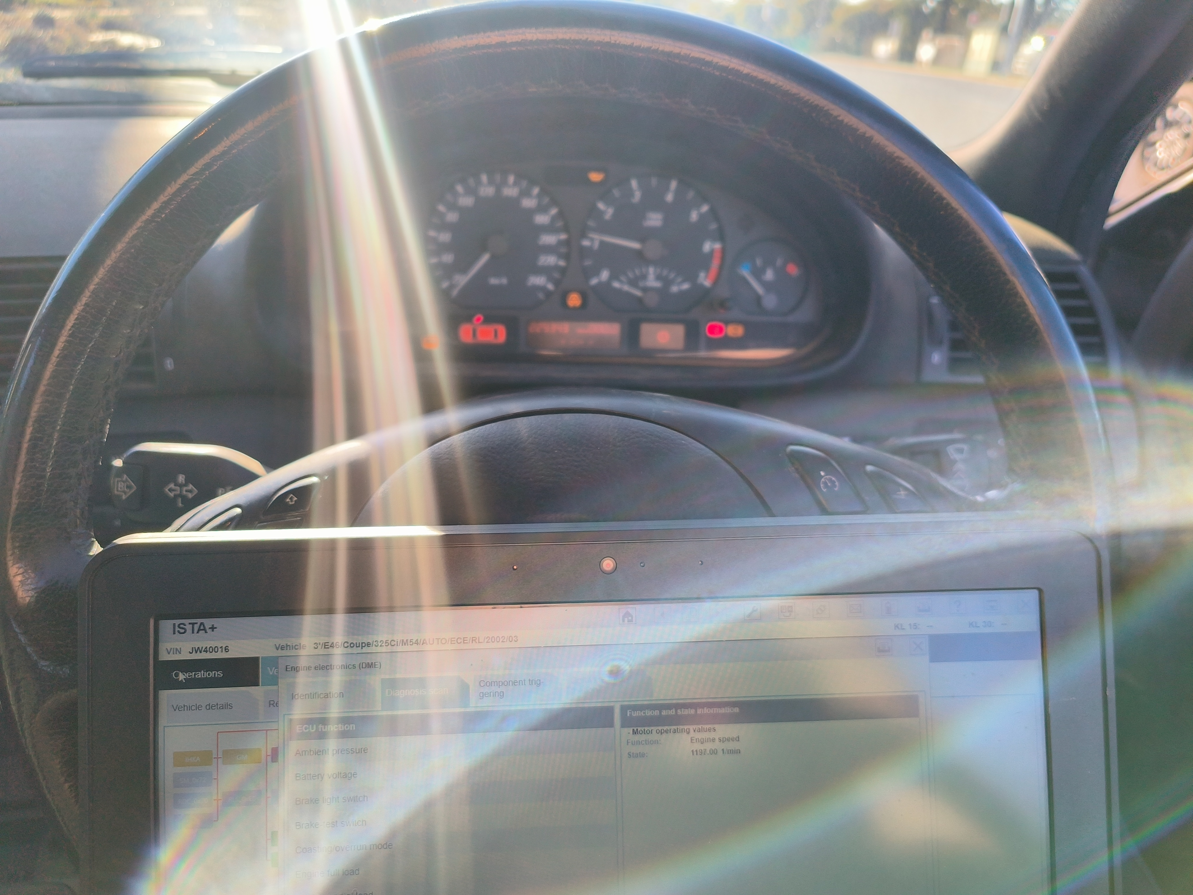
I know, the glare - it is what it is the picture still gets it's point across.
Outro
During this process I was actually surprised by the amount of issues this solved that I figured were likely unrelated. This car had no communication with the ABS and ESC modules at all, whereas with this repaired cluster they didn’t flat out start working, but they did actually show up as not responding in ISTA+, which is a promising sign – I have some hope it’ll be possible to make those work now. I also couldn’t read this car’s VIN over ISTA+, and had to manually type it in to run any sort of diagnostics. After replacing the cluster, it also can now read that out fine.
It also appears to have solved the intermittent no start, (update: no it hasnt. ignition switch) but as tends to be the deal with intermittent issues I won’t actually 100% know for sure unless it does it again, however given I tried to start it with the old cluster and it didn’t start when I actually replaced the cluster, and proceeded to start fine as soon as I swapped it out for this one, I’m fairly sure that was the issue.
Bonus credits/Resources
I actually found these after I’d already figured out it was a capacitor issue since search engines can be terrible at giving you the actual info you’re after sometimes, so I only actually had these pop up after specifically searching the phrase “e46 cluster capacitors”. Regardless, a quick shout-out to bimer21 on the E46fanatics forum who worked this out in 2016 (forum thread here https://www.e46fanatics.com/threads/dead-cluster-under-2-fix.1102729/), as well as Agent24 on YouTube who has a whole 2 hour video on the process if you’re more of a visual learner which you can watch at https://www.youtube.com/watch?v=uoRfGtUAjH8 – there’s probably other resources hiding too if you look for them. No matter whose guide ends up being the one you use, the most important thing is that it’s another car kept on the road. Good luck!